Although there have been many articles written about the general changes introduced by Amendment 4 of BS 7671, this article from the experts at Unicrimp will consider in more detail two specific changes around protected escape routes and the position of devices for protection against fault current, and their likely implications.
Protected escape routes
The changes to the requirements of Section 422 introduced in 2018, and further changed in a subsequent corrigenda, has now been further amended in to provide greater clarity on the specific locations where the requirements of Section 422 apply.
The updated Regulation 422.2.201 now details the specific locations where cables or electrical equipment must not be installed. These locations are now limited to fire-fighting shafts and protected stairways. A fire-fighting shaft comprises a firefighting stairway and, where relevant, a firefighting lobby.
That same regulation now details the types of cables permitted in protected corridors. Regulation 422.2.1 details the following permitted cables:
· Fire-resistant cable meeting the requirements of Regulation 560.8.1. These are:
o MI cable systems conforming to BS EN 60702-1 and 2 and BS EN 60332-1-2;
o Fire-resistant cables conforming to IEC 60331-1, 2 and 3 and with BS EN 60332-1-2;
o Fire-resistant cables complying with test requirements of BS EN 50200, BS 8434 or BS 8491, appropriate for the cable size and with BS EN 60332-1-2;
o A wiring system maintaining the necessary fire and mechanical protections.
· Bunched cables with resistance to flame propagation according to the requirements of the relevant parts of BS EN 60332-3 series, or
· Single wires or cables, where cable management systems according to indents d) to g) in Regulation 422.2.1 are used, tested to BS EN 60332-1-2. These cables are to be of limited smoke production and shall have limited halogen acid gas content not exceeding 0.5% when tested in accordance with BS EN 60754-1.
Where single-core wires or cables are referenced, indents d) to g) cover:
· Non-flame propagating conduit systems conforming to BS EN 61386.
· Non-flame propagating cable trunking and ducting systems conforming to BS EN 50085.
· Non-flame propagating cable tray and ladder systems conforming to BS EN 61537.
· Powertrack systems conforming to BS EN 61534.
Note 2 states that ferrous metal (steel) is deemed to be an example of a material having limited smoke production.
Designers should continue to ensure that care is taken in limiting the type and nature of cables and cable management systems where they are to be installed in protected escape routes.
Position of devices for protection against fault current
Section 434 in BS 7671 covers Protection against fault current. Within that overall section, Regulation Group 434.2 covers where protective devices should be provided to provide protection against fault current.
The general requirement states that, ‘…protection against fault current shall be installed at the point where a reduction in the cross-sectional area or other change causes a reduction in the current-carrying capacity of the conductors, except where Regulation 434.2.1, 434.2.2 or 434.3 applies.’
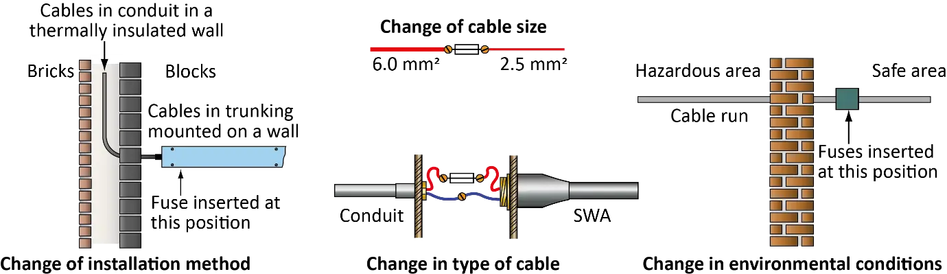
Figure 1 Examples of where a protective device may need to be installed.
This general regulation, therefore, provides clear requirements that show where protection against fault current must be applied (see Figure 1). However, where a location does not present either a fire risk or an explosion risk, Regulations 434.2.1, 434.2.2 and 434.3 do permit some variation on this requirement.
Regulation 434.2.1 allows for the position of the protective device to be varied from that detailed in Regulation 434.2 under specific conditions. These conditions are:
· that the conductor must not exceed 3 m; and
· be selected and erected to be inherently short-circuit proof and earth fault proof; and
· be installed in such a manner as to reduce to a minimum the risk of fire or danger to persons.
All of the three conditions must be met for compliance.
BS 7671 defines ‘Inherently short-circuit and earth fault proof as, ‘The state of electrical equipment or assembly protected against short-circuits and earth faults due to design and erection provisions.’
The second condition of 434.2.1, requiring the conductor to be inherently short-circuit proof and earth fault proof, is a change from that which previously existed; i.e. requiring the cable to be installed in such a manner as to reduce the risk of fault to a minimum. This change is more absolute and requires the installer to take such additional measures to ensure the inherently short-circuit and earth fault proof requirement is met.
How this requirement is met is not detailed in the standard, and it is for the installer to decide on the way(s) in which the requirement is met.
By way of example, consider a condition where two supplies are required, one for a consumer unit and one for an EV charger. The consumer unit is supplied with meter tails having a cross-sectional area of 25 mm2, the EV charger circuit has tails having a cross-sectional area of 6 mm2. A connector block (see Figure 2) is used to supply both circuits.
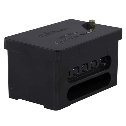
Figure 2 Scolmore Click connector block
Since a smaller cable is being used for the supply of the EV charger, Regulation434.2 applies and a protective device must be installed at the point of change in the current-carrying capacity of the cable. However, where there is no fire or explosion risk, Regulation 434.2.1 may be used to alter the point at which the protective device is installed if it meets the three specific conditions detailed.
Conclusion
There have been many changes made to BS 7671 in Amendment 4. Subsequent articles will consider in further detail the implication of further changes.