A Guide To Steel Wire Armoured (SWA) Cables: Construction, Termination, And Installation
Steel wire armoured (SWA) cables are a cornerstone of robust electrical installations, providing outstanding mechanical protection and long-term durability. Jake Green, Head of Technical Engagement at Scolmore Group - which includes the Unicrimp cable accessories division - considers the basic structure of SWA cables, their means of installation and ‘making off’, and the relevant regulations which might apply to their installation.
Steel wire armoured (SWA) cables have been in use for many decades. Steel wire armoured cables were first introduced in the 19th century for telegraphy, and modern (PVC insulated and sheathed) SWA cables were introduced in the 1960s. Cross-linked polyethylene (XLPE insulated and sheathed) cables were then introduced in the 1970s.
There are three current British Standards which specify the requirements for types of SWA cables used within the electrical installation industry:
· BS 5467: 2016 Electric cables. Thermosetting insulated, armoured cables of rated voltage of 600/1000 V and 1900/3300 V for fixed installations.
· BS 6724: 2016 Electric cables. Thermosetting insulated, armoured cables of rated voltage of 600/1000 V and 1900/3300 V for fixed installations, having low emission of smoke and corrosive gases when affected by fire.
· BS 7846: 2015 Electric cables. Thermosetting insulated, armoured, fire-resistant cables of rated voltage of 600/1000 V for fixed installations, having low emission of smoke and corrosive gases when affected by fire.
Structure
Steel wire armoured cable is relatively complex, and it is this complexity which requires the installer to take care when terminating the cable.
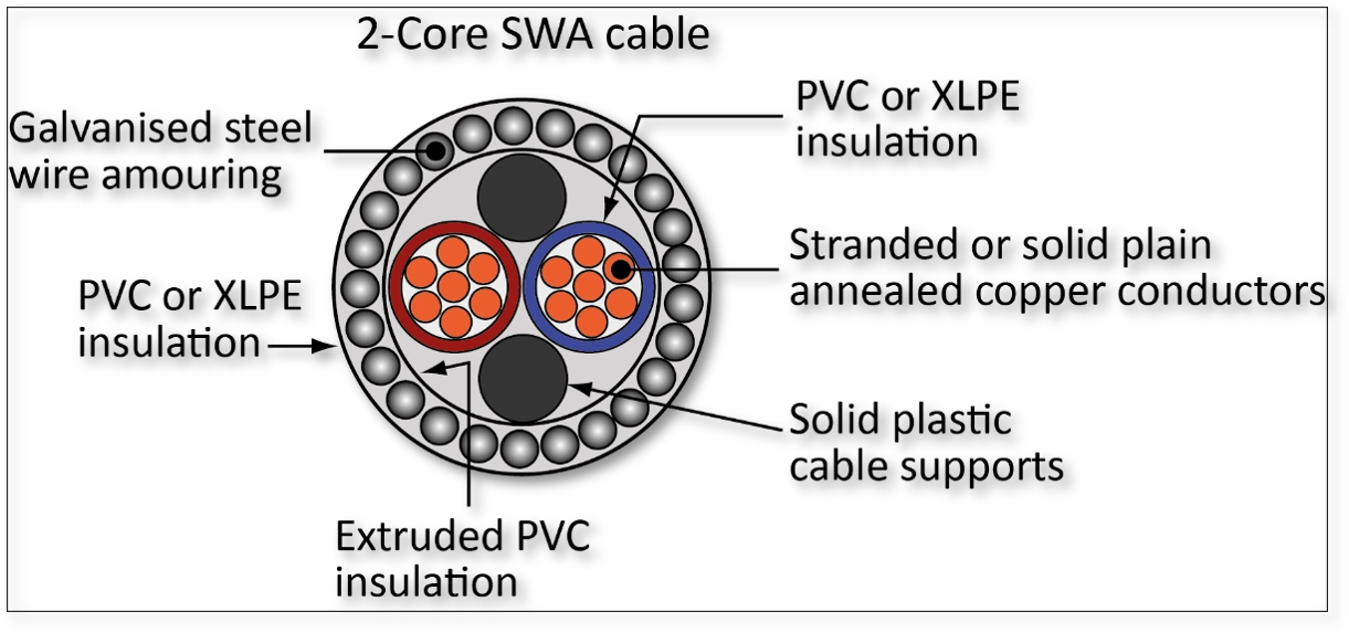
Figure 1 End-view of typical SWA (image courtesy of TJ Bratley)
The outer sheath is either PVC or XLPE, as is the insulation surrounding the conductors. The insulated conductors are surrounded by extruded PVC or wrapping and then galvanised steel wire armouring is wrapped helically around the cable before the outer sheath is added.
Terminating the cable
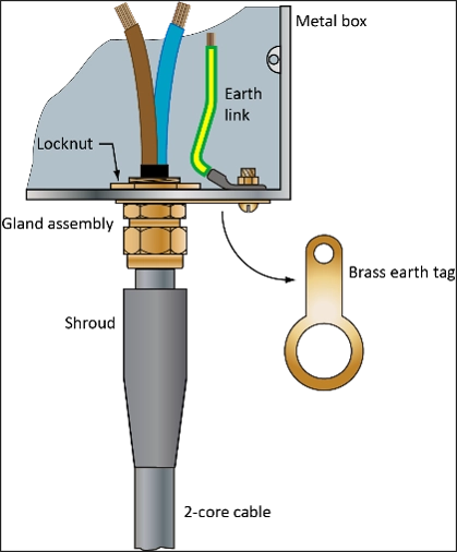
Figure 2 Terminated SWA (image courtesy of TJ Bratley)
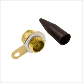
Figure 3 Gland assembly and shroud
Regulation 526.1 requires amongst other things, that, ‘Every connection…between a conductor and other equipment shall provide durable electrical continuity and adequate mechanical strength’.
Terminating an armoured cable requires the installer to take care in ensuring that the cable is correctly terminated using all elements of the gland assembly (shroud, gland assembly, earth tag (banjo) and locknut (ring)).
To ensure that continuity is maintained the gland assembly must be terminated in such a way that the armouring is robustly held and that electrical continuity is maintained. This is done using the ‘banjo’ and creating the ‘earth link’ as seen in Figure 2. Even where there is a separate protective conductor in the cable, the armouring remains an exposed-conductive-part and continuity should be maintained.
It should be noted that it is rarely necessary for a SWA cable to require a separate protective conductor from the armouring. The CSA of the steel armouring greatly exceeds the CSA of any internal copper conductor.
Installation
Size for size armoured cables are heavier than non-armoured cables. It is important that the means of support are adequate to ensure that such cables do not become a hazard (522.8.4).
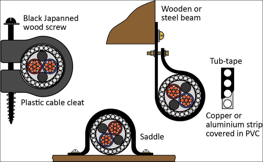
Figure 4 Support types for SWA cables (image courtesy of TJ Bratley)
Regulation Group 522.8 detail the group of requirements which are likely to apply most commonly to the installation of any cables. In particular, Regulation 522.8.10 requires armoured cables to be used where cables are buried in the ground, unless those cables are installed in conduit or ducting. Even where armoured cables are buried in the ground, they should be at such a depth as to avoid inadvertent damage. The general guidance is that any cables should be buried at a depth of at between 450 mm to 600 mm. A reasonable guide is to assume the double depth of a spade.
Where armoured cables are installed on ladder rack or cable tray, the support systems of the containment system must be adequate to meet the requirements for the combined weight of all cables installed.
Where cables are buried warning tape should be used to warn persons digging that a live cable is in close proximity.
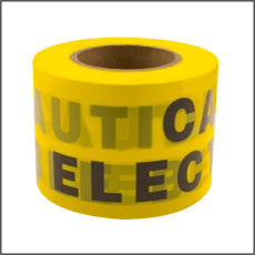
Figure 5 Electrical warning tape
There remain specific requirements for the use of armoured cables in Part 7 of BS 7671, and the designer/installer should make sure they are familiar with the relevant Sections where this is the case.
Unicrimp cable accessories for SWA cables
In addition to correct containment and support systems, the selection of appropriate fixings, cleats and glands plays a key role in ensuring SWA installations remain mechanically secure and compliant with BS 7671.
Unicrimp provides a broad portfolio of cable accessories designed to support robust SWA installations across commercial and industrial environments.
Fire-rated fixing solutions
Within its Q-Fire range, Unicrimp offers All-Round Banding - a pre-punched steel banding system designed to provide secure, fire-resistant cable support. Suitable for cables, conduit, trunking and containment, the banding can be easily cut and formed on site, with pre-punched holes allowing quick fixing using screws, bolts or nails.
The range is available in non-coated galvanised steel (12mm and 17mm widths), as well as LSF-coated options in black (12mm and 17mm) and red or white (12mm), all supplied in 10-metre coils.
Metal cable cleats
Also forming part of the Q-Fire collection, metal cable cleats provide additional mechanical restraint where SWA cables are installed on ladder rack, tray or directly to structure. Manufactured from carbon steel with a durable polyester coating, they offer high-temperature resistance, impact strength and long service life.
Available in sizes covering 12.6–15.2mm and 15.1–17.8mm cable diameters, the cleats are compliant with BS 7671 Regulation 521.10.202 and are particularly suited to commercial, industrial and higher-risk installations where circuit integrity and secure cable retention are critical.
Cable glands and termination
Correct termination remains fundamental to maintaining electrical continuity of the armour. Unicrimp’s Q-Crimp range incorporates over 19 product categories, including a comprehensive selection of cable glands suitable for SWA applications.
Brass BW, CW and AE1W glands are manufactured to current approvals and comply with BS 6121. The latest three- and four-part brass gland designs incorporate a brass olive, enabling effective clamping across varying armour sizes and grades. These are available in 20(s)mm, 25mm, 32mm and 40mm sizes and are supplied in packs of two.
Conclusion
SWA cables are widely used within the electrical industry and provide significant levels of mechanical protection across a broad range of installations. However, their performance is dependent not only on correct cable selection, but also on appropriate installation methods, secure fixing and compliant termination.
Ensuring adequate mechanical support, maintaining electrical continuity of the armour, and selecting suitable glands, cleats and fire-rated fixings are all essential elements of a safe and durable installation. By combining correct design principles with quality, standards-compliant accessories, installers can ensure SWA systems continue to perform reliably under both normal operating conditions and in the event of fire.